


英维思(3008, 3625, 3508E.3721, 3700A 4351B)
本特利(3500/42M, 3500/ 22M, 3500/ 95.3500/05)
黑马(F3330, F3236, F6217, F7126, F8621A)
福克斯波罗(FBM203, FBM204, FBM217, FMB231)
AB: (1746 1747 1756 1770 1771 1785触摸屏2711系列CPU PLC)
普罗索芙特PROSOFT MVI46/56/69, AB旗下,跟AB模块
瑞恩RELIANCE模块,卡件
飞利浦EPRO MMS6210/ 621…. PR6423/003-031
美尔托Meltal MT1102-02-00, MS3101-00-00, MS3102-01-00
横河YOKOGAWA AAI, ADV, ADI, ANB, AMM, SB, PW(型号开头),卡件模块(CPU,电源,输出,PLC)
摩尔MOORE Q开头, 3开头模块,像电视显示器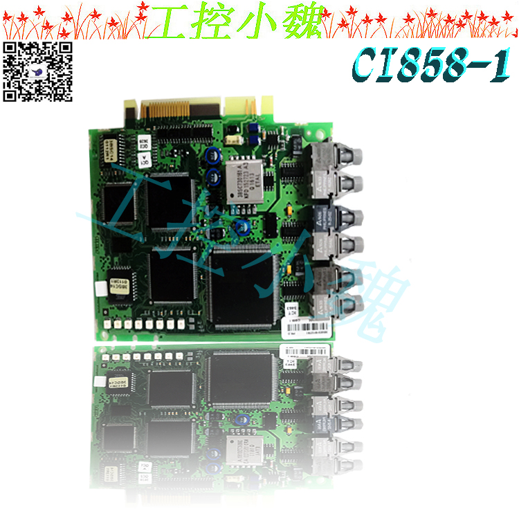


你的满意是我们不懈的追求;
你的口碑相传是对我们好的回报
Bearing temperature (if applicable): each sliding support bearing and thrust bearing shall be equipped with bearing pad temperature measuring points; The working face and non working face of thrust bearing shall be equipped with temperature measuring points at the same time.
Gearbox shell vibration (if applicable): a pair of X/Y direction shell vibration measuring points shall be provided at the support bearings of input and output shafts of each gearbox; Bentley 330400 series piezoelectric vibration acceleration sensor is used for measurement.
2.3500 Configuration requirements
Each key compressor unit is equipped with Bentley 3500 frame
Each Bently 3500 rack is configured with redundant 3500/15 power modules
3500/22M Transient Data Interface Module (RJ45 Network Interface) is configured in each Bentley 3500 rack
For the above Keyphasor measurement points, the Bently 3500 rack of each unit is equipped with corresponding 3500/25 Keyphasor modules
The 3500/42M monitor module must be configured for the above measuring points of shaft vibration, shaft displacement, bearing vibration and shell vibration
(If applicable), the above bearing temperature measuring points need to be configured with corresponding 3500/60, 61 temperature monitoring modules, or 3500/62 process quantity monitoring modules
Each monitoring channel (shaft vibration, shaft displacement and bearing vibration) is equipped with two relay output channels of D-type; Use 3500/32 (4-channel) or 3500/33 (16 channel) relay modules
Each Bently 3500 rack is configured with a 3500/92Modbus communication gateway
For units working in hazardous areas, 3500 monitor modules connected to field signals shall be equipped with built-in safety barriers; 3500/04 intrinsically safe grounding module shall be configured in the 3500 rack. API618 reciprocating compressor
For units working in hazardous areas, Bentley sensors and monitoring systems should have the option of multi agency approval units. There is no requirement for the units working in the safe area.
1. Requirements for measuring point configuration
Multi event Keyphasor: A multi event Keyphasor runner MEW is installed at the drive end of the reciprocating compressor to measure the Keyphasor reference signal of the reciprocating compressor. The multi event Keyphasor runner can be Bentley standard multi event runner MEW, or the reciprocating compressor manufacturer can customize and design the multi event Keyphasor runner according to Bentley's engineering experience in multi event Keyphasor runner based on its own equipment structure design characteristics. The multi event Keyphasor signal is measured by Bentley 3300XL series eddy current sensor.
Crankcase vibration: a vibration speed sensor is arranged on the horizontal axis of each main bearing between two cylinder rows of the reciprocating compressor crankcase to measure the crankcase body vibration. Bentley 330500 series Velomitor piezoelectric vibration speed sensor is used when the working speed of the reciprocating compressor is less than 500 rpm; Bentley 190501VelomitorCT piezoelectric vibration speed sensor is used when the working speed is lower than 500rpm.
Crosshead vibration: redundant acceleration sensors are configured on the vertical plane at the midpoint of crosshead movement of each cylinder of the reciprocating compressor to monitor the impact event of reciprocating components; Bentley 330425 acceleration sensor is used for measurement.
Piston rod position: a pair of mutually perpendicular piston rod position measuring points shall be configured in the horizontal and vertical directions of each cylinder of the reciprocating compressor perpendicular to the piston rod plane; Bentley 3300XL series eddy current sensor is used for measurement. For reciprocating compression piston rod measurement.
Cylinder dynamic pressure: each cylinder of the reciprocating compressor is equipped with two cylinder pressure measuring points (suction and exhaust), which are measured by Bentley 165855 cylinder pressure sensor.
Bearing vibration: each main bearing in the crankcase of the reciprocating compressor is equipped with a speed sensor to measure the bearing vibration. Bentley 330500 series Velomitor piezoelectric vibration speed sensor is used when the working speed of the reciprocating compressor is less than 500 rpm; Bentley 190501VelomitorCT piezoelectric vibration speed sensor is used when the working speed is lower than 500rpm.
Bearing temperature: each main bearing is equipped with a temperature sensor to measure the bearing temperature.
Air valve temperature: each air valve (suction valve and exhaust valve) of the reciprocating compressor cylinder is equipped with a temperature measuring valve temperature.
Gearbox shell vibration (if applicable): a pair of X/Y direction shell vibration measuring points shall be provided at the support bearings of input and output shafts of each gearbox; Bentley 330400 series piezoelectric vibration acceleration sensor is used for measurement.
Motor pad vibration: each rolling support bearing is equipped with two pad vibration measuring points (installed horizontally and vertically), which are measured by Bentley 330500 series Velomitor piezoelectric vibration velocity sensor.
2. Bently 3500 configuration requirements
Each key compressor unit is equipped with Bentley 3500 frame
Bently redundant 3500/15 power module
Bently 3500/22M Transient Data Interface Module (RJ45 network interface)
Bently 3500 rack of each unit is configured with corresponding 3500/25 Keyphasor module
Reciprocating compressor crankcase vibration, crosshead vibration, and bearing vibration are equipped with corresponding 3500/70M monitor modules
The measuring point of piston rod position shall be configured with corresponding 3500/72M monitor module
The 3500/77M Monitor Module for Reciprocating Compressor Cylinder Dynamic Pressure Configuration
Bearing temperature and air valve temperature measuring points shall be configured with corresponding 3500/60,/61,/62 or/65 monitor modules
For gearbox housing vibration and motor pad vibration, corresponding 3500/42M monitor module shall be configured
Each monitoring channel is equipped with two relay output channels; 3500/32 (4-channel) or 3500/33 (16 channel) relay modules Bently use a 3500/92Modbus communication gateway. For units working in hazardous areas, 3500 monitor modules that access field signals must have built-in safety barriers; 3500/04 intrinsically safe grounding module shall be configured in the 3500 rack.
The product quality of Bently 3500 vibration protection instrument and condition monitoring system for rotating machinery strictly follows the American API670 standard.
Bentley vibration monitoring training course, the main content of this course: displacement sensor noise source
Noise is a signal you don't need, but in most cases, noise is unavoidable in the measurement process. Although the noise cannot be removed during the measurement, the noise can be reduced to a small degree of Z so that it does not affect your signal analysis. To achieve this, it is necessary to understand the source and characteristics of noise. Noise is an undesirable signal component, which can distort data and hinder your ability to extract machine state information from data. The information contained is independent of the machine state. Noise can be introduced from a part of the measurement system, but each part of the system has different sensitivity to noise. Bently displacement sensor includes Bently 3300 series eddy current sensor probe.
Noise source of displacement sensor
1. Installation: sensor bracket vibration 5. deviation – mechanical deviation
Noise source of displacement sensor
Runout – electric deviation alloy element non-uniform conductivity non-uniform magnetic conductivity non-uniform axis material local stress concentration There is a local magnetization area on the axis
Noise source of displacement sensor
runout and running time – short mechanical and electrical deviations are stable
Noise source of displacement sensor
runout and running time – medium time thermal and process parameters change Displacement sensor noise source
Deviation (runout) and running time – some noise sources (rust, corrosion, local magnetization area, etc.) change for a long time
Noise source of displacement sensor
Rotor bending: Why is the rotor bending often treated as deviation, and the rotating bending generates 1X signal? In mechanical fault diagnosis, 1X component of dynamic vibration signal is useful. When studying the synchronous response of machinery, the signal generated by bending shall be compensated,
Noise source of displacement sensor
Rotor bending – if the rotor bending is permanent, it can be treated as 1X noise source – some bending is unstable and will change with temperature and load. If such bending is repeatable, it can also be treated as noise. The bending caused by the shaft crack changes with the crack growth and has no repeatability. All three timers use an interrupt IRQ5. The timer interrupt status register is used to determine which timers started interrupts. The Interrupt Status Register is a general-purpose input register located outside of 82C54, offset 31h from the power management base I/O address. The interrupt status register address can be found for device ID 7113h and vendor ID 8086h by first determining the PCI configuration base address. The power management base I/O address can be found by reading an offset of 40h from this PCI configuration address. The timer interrupt status register bit is located at the base I/O address at offset 31h of power management, bits 5, 6, and 7 (see Figure 4-2). The bytes of offset 31h read from the power management basic I/O address are used to obtain these bits. Bits 5, 6, and 7 correspond to timers 2, 1, and 0 respectively. In order to interrupt the status register of the timer, first write zero (0) to the general-purpose output register. The offset 37h input/output address bits 3, 4, and 6 (not bits 3, 4, and 5) on the power management base. Then write 1 in the same bit of the re enable timer interrupt status register. Bits 3, 4, and 6 correspond to timers 2, 1, and 0 interrupt IRQ5 using PC/AT's standard program timer, respectively. See Appendix D for an example of using the 82C54 timer. VMIVME-7698 timers are mapped to the I/O address space starting at $500. Refer to Table 4-1 Timer, which consists of three 16 bit timers and a control word register (see Figure 4-4) and is read/written via the 8-bit data bus. Timer 0, 1 and 2 are functionally equivalent. Therefore, only
A single timer is described. Figure 4-5 is a block diagram of a timer. Each timer functions independently. Although the control word displayed in the timer block is not a part of the timer, its contents directly affect the working mode and function of the timer. As shown in Figure 4-5, when latched, the status register contains the contents of the current control word register and the current status count flags of the output and load (the status word can be obtained through the Read Back command, see the "Reading" section on page 059). The timer is marked TE (timer element). It is a 16 bit synchronous and preset down counter marked with OLM and OLL blocks that are 8-bit output latches (OLs). The subscripts M and L represent 00 significant bytes and 0 low significant bytes. These pins usually track the TE, but when a command is received, they lock and hold the current count until the CPU reads the count. When the latch count is read, the OL register will continue to track TE. When reading the OL register, you must perform two 8-bit accesses to retrieve the full 16 bit value of the timer because only one latch is enabled at a time. TE cannot read; Read the count from the OL register. A single interrupt, IRQ5, is used by all three Timers. A Timer Interrupt Status register
is provided in order to determine which Timer(s) initiated an interrupt. The interrupt
status register is a general-purpose input register located, external to the 82C54, at
offset 31h from the Power Management base I/O address. The interrupt status
register address can be found by first determining the PCI Configuration base address
for Device ID 7113h and Vendor ID 8086h. The Power Management base I/O address
can be found by reading offset 40h from this PCI Configuration address. The Timer
Interrupt Status register bits are located at offset 31h from the Power Management
base I/O address, bits 5, 6, and 7 (refer to Figure 4-2). A byte read of Offset 31h from the Power Management base I/O address is used to
obtain these bits. Bits 5, 6, and 7 correspond to Timers 2, 1, and 0, respectivelyIn order to clear the Timer Interrupt Status register, first write zeros (0’s) to the
general-purpose output register located at offset 37h of the Power Management base
I/O address bits 3, 4, and 6 (Not bits 3, 4 and 5). Then write ones (1’s) to these same
bits to re-enable the Tim
;ABB 3HNA000512-001
ABB CI627
ABB DI620
ABB AI625
ABB DO620
ABB BRC300
ABB AO610
ABB BRC300
ABB AI835
ABB DSPC172H
ABB 3HAC17326-1/02
ABB DSAI130
ABB
ABB DSPC170
ABB CI626
ABB DI610
ABB DSAI146
ABB SC520 3BSE003816R1
ABB PFSK151
ABB PM511V16 3BSE011181R1
ABB 3HNA000512-001
ABB SPCJ4D34-AA
ABB IMASI23
ABB DI651
ABB IMASI23
ABB IMDSI14
ABB PPD113B01-10-150000
ABB CI541V1 3BSE014666R1
ABB CI627
ABB SC520 3BSE003816R1
ABB CS513 3BSE000435R1
ABB PM802F
ABB SC510 3BSE003832R1
ABB 5SHY5045L0020
ABB DI620
ABB CI522A 3BSE018283R1
ABB PM630
ABB CI534V02 3BSE010700R1
ABB PCD231B101
ABB SC520M 3BSE016237R1
ABB INNPM12
ABB PM803F
ABB DO630
ABB PM633
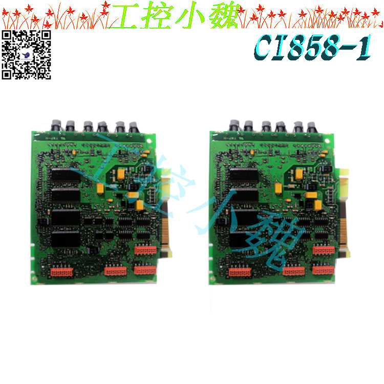
ABB CI855-1
ABB 5SHY3545L0009
ABB PPD113B03-26-100110
ABB PPD113-B03-23-111615
ABB IMBLK01
ABB SC610
ABB PM633
ABB RF615 RC610
ABB DO620
ABB AI625
ABB IMDS014
ABB BRC300
ABB PCD231B
ABB 5SGX1060H0003
ABB PM632
ABB P-HA-RPS-32200000
ABB PFCL201C 10KN
ABB PM645B
ABB PPC902CE101
ABB PP846A
ABB TC630
ABB 5SHY3545L0014
ABB AO610
ABB DSDP140B 57160001-ACX
ABB UAD149
ABB 216EA61b
ABB BRC300
ABB 5SHX2645L0004
ABB 07AC91D
ABB AI835
ABB 5SHX2645L0004
ABB SPHSS13
ABB PPD113B01-10-150000
ABB DSPC172H
ABB FI830F
ABB 5SHX1060H0003
ABB ASE2UDC920AE01
ABB 5SHX2645L0004
ABB 3BHB003688R0001
ABB DSPC172H
ABB 800PP846A
ABB 3HAC17326-1/02
ABB PM511V16
ABB PM864AK01-eA
ABB PFSK152
ABB SR511 3BSE000863R1
ABB IW93-2 HESG440356R1 HESG216678/B
ABB M2004HW
ABB 216DB61
ABB IMHSS03
ABB DSQC202
ABB PFEA113-65
ABB P-HA-RPS-32200000
ABB PU515A
ABB 5SHY5045L0020
ABB AI625
ABB IMFECI2
ABB 504994880
ABB 5SHY3545L0009
ABB DSAI130
ABB CI535V30 3BSE022162R1
ABB PP836A
ABB MB510 3BSE002540R1
ABB PFSK152
ABB CI535V30 3BSE022162R1
ABB HIEE300024R4 UAA326A04
ABB CI871K01
ABB DO620
ABB PPC907BE
ABB PM864A
ABB UAA326A02
ABB SB822
ABB PCD235A101
ABB 216EA62
ABB DSAI130D
ABB UNS0119A-P V101
ABB 5SHX1060H0003
ABB TAS.580.0560G00
ABB REX010
ABB 5SHX1060H0003


 微信二维码
微信二维码